For most repairmen, the machining of cylinder head seats is an even more mysterious process than, for example, honing. It is in the machining of seats that 100-year-old myths still prevail among engine mechanics, not only preventing the correct repair of seats, but even simply understanding the essence of this type of machining. Meanwhile, being captive to old-fashioned techniques, not knowing either the technology or the equipment for machining, it will not be possible to repair the cylinder head of a modern engine.
It is even more difficult when a new machine for machining seats needs to be selected to equip the workshop. How to make the right choice from dozens of possible options, and not get into trouble, not get into a puddle, not get caught on a rusty spoon or a beautiful wrapper? Especially since such examples already exist, unfortunately…
INTRODUCTION
 Let’s first consider the main myths that have been circulating in valve seat processing for 100 years. There are three of them:
1. Valve seat repair definitely includes lapping of valves to the seats (how could it be otherwise?) To do a good repair, you must take as much abrasive paste as possible, and then lap the valve to the seat as long and hard as possible. A variation of this 100-year-old myth (in those distant times there were simply no repair machines), in an attempt to give it a more civilized and modern look, is this — yes, we will only lap slightly, exclusively to control the mating of the valve with the seat. Which is the same thing, only a side view. Naturally, the fact that abrasive will penetrate the seats, which will quickly eat the valve, and that lapping will destroy the correct profile of the seat, which all together will lead to a reduction in the engine life by several times, is of less than no interest to a real lapper. Accordingly, explaining to a lapper that none of this can be done in modern engines is usually impossible in principle and by definition.
2. The quality of the seat repair is definitely determined by checking for kerosene — if kerosene poured into the combustion chamber leaks through a closed valve, then the repair is done very poorly. And such a defect can only be corrected by long and fine lapping (see point 1). Explaining to an inspector who is dissatisfied with the quality of the repair that the engine combustion chamber contains not liquid kerosene, but air or combustion products, which have completely different properties, is usually also impossible in principle and by definition.
3. No seat processing technology is needed. A super mechanic has everything he needs in his garage — and, first of all, a whole set of toothed cutters. If necessary, he will make any head in a luxury manner, and will bite any seat. What? How is that impossible? But he is a super mechanic! He has an eye like a diamond and hands of pure gold! But, unfortunately, all these qualities mean nothing if there is no understanding of the process and no desire to understand why this 100-year-old “technology” cannot be used to repair modern engines.
So, jokes aside. If you, dear reader, belong to one of the above groups of fans of grinding, kerosene testing and/or manual toothed cutters, then we can safely advise you not to read or watch anything further here — it is definitely not for you. For everyone else, as usual, there will be our traditional exclusive material.
Part 1. GENERAL INFORMATION ON DAMAGE AND MACHINING OF SEATS
Problem
Everyone knows that during long (and sometimes not so long) operation of the engine, the mating surfaces (the so-called friction pairs) of the moving valve with the cylinder head (seat and guide) wear out. Wear causes loss of valve tightness and instability of engine operation, especially at idle. The rule, long known to competent diagnosticians — when it is not possible to overcome this engine instability by electronic methods (and in this fight, some of the most advanced ones manage to replace a bunch of sensors and even the engine control unit!), there is every reason to believe that the valve mechanism needs to be repaired. Although, of course, diagnostics of wear and damage to the valve mechanism is also a completely separate and different story …
Solution
Repair of the valve mechanism, of course, involves restoring its tightness by restoring the geometry of all worn parts — first of all, the valve chamfer and seat. But where will we have the technological base from which we will accurately straighten the seat? It is no secret that the seat must be machined absolutely precisely in one axis (coaxially, concentrically) with the valve guide bushing. That is correct, but it is precisely with the technological base that we may have a big problem – the valve guide is most likely worn out if the seat is worn out. And it often requires replacement, otherwise the seat cannot be corrected (or better yet, not even corrected — it will be worse than before). And the valve? The valve needs to be changed only if the stem is worn out, which does not happen so often. Therefore, the valve, unlike the guide, can be repaired — by grinding the working chamfer (although this is a topic for a separate conversation).
If everything is prepared — that is, the valve guide is new, and the valve chamfer shines even better than new, then we proceed to the practical side of the matter.
Implementation of the process
There are 2 fundamentally different ways of processing the seat — grinding and turning (milling). It so happened that grinding is used only where the cylinder head cannot be removed and installed on a machine — and these are all sorts of giant engines that are repaired using their own separate technologies. All other vehicle engines prefers turning — and that is what we will consider.
However, turning is not the same as turning. Because a manual toothed milling cutter — it also turns (and how!). However, we will leave this method only to the most real garage workers. And further we will consider only processing on specialized machines. Why? For the simple reason that a manual toothed milling cutter is in principle not capable of meeting any of the necessary technological requirements for the process of processing saddles. What are they? Yes, like these …
Part 2. BASIC REQUIREMENTS TO THE TECHNOLOGICAL PROCESS OF SEAT MACHINING
To understand the issue, you must first understand…
The main stages of seat processing
1. Accurate installation of the head on the machine.
With all machines without exception, it is necessary to ensure a strictly vertical position of the guide bushing hole during installation. For this, everyone uses special position sensors — this can be something like a bubble level or even a precise electronic device. The times when this alignment was done by the gap between 2 guide rods-pilots — one in the bushing and the other in the machine spindle, have sunk into oblivion due to complete crudeness and inaccuracy. Well, and those who still believe that the bushing during processing can take any position other than vertical, are simply not specialists in this type of processing (and in other types, perhaps, too).
2. Centering the tool
The most important operation, around which disputes have not subsided for 25 years, hundreds of copies have been broken and tens of liters of competitors’ blood have been drunk. Why is this so important?
Because the cutter must adjust the seat strictly in the axis of the guide sleeve — otherwise the valve chamfer will then sit on the seat sideways. If this happens, then not only will there be no tightness, but also rapid wear of the guide, and with it the seat itself, will be guaranteed by lateral loads on the valve.
In other words, it is necessary to center the place where the cutter is fixed (in most machines this is the tool holder) with the hole of the guide sleeve — to ensure concentricity or coaxiality of the circle along which the cutter will rotate, with the hole of the guide. Only in this case can the seat be turned correctly.
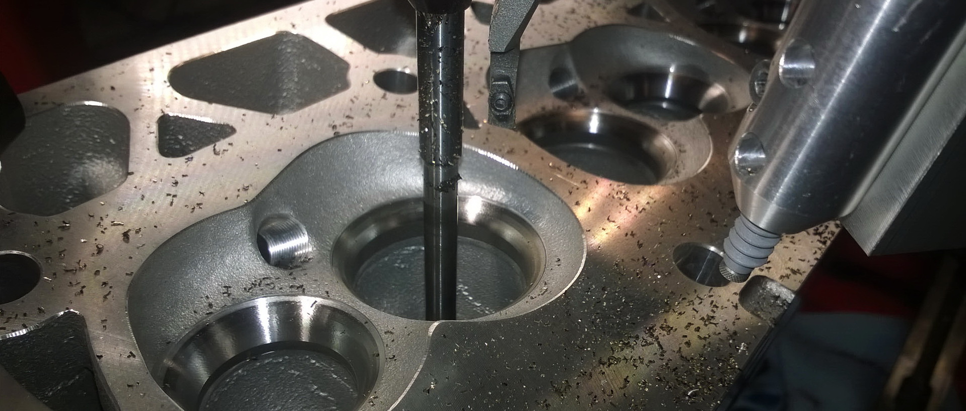
3. Turning
If the centering is done correctly, then turning will be just a matter of technique. The vast majority of machines use a so-called profile cutter, which cuts all three chamfers of the seat at once — the working and two adjacent ones. With high seat hardness, single-angle cutters are sometimes used sequentially. Well, and in some CNC machines at one time it was fashionable to show off their coolness and sharpen with a so-called point cutter, forming a saddle profile specified by the program. But this technology failed in engine repair due to fantastically slow processing.
In the overwhelming majority of machines, the vertical feed of the spindle with the cutter is done manually using a handwheel, although it is not in CNC machines for obvious reasons. Some manufacturers add a so-called micro screw to the manual feed. It is believed that this improves the quality of processing, but judging by the fact that micro screws have not become widespread, not all manufacturers agree with this.
In other words, there are some tricks when turning a saddle, but they are not as critical compared to centering, which actually determines the accuracy of the entire machine. How to do it right? This is where the most interesting part begins, and …
Option 1 — a hinged bayonet scheme for processing the saddle. Main features (briefly):
1. Extremely simple and precise centering (coaxiality, concentricity) of the tool in the guide bore is easily achieved with a dead cone pilot
2. With a hinge between the spindle and the cutter, the pilot is used not only for centering, but also as the main element of the machining system.
3. As a result, the entire rigidity of the system is determined by the thin pilot, not the thick spindle.
4. Insufficient machining rigidity (with a thin pilot) does not allow for precise machining of seats in cylinder heads with small valves.

The magic bayonet hinge.
Hundreds of copies have been broken and tens of liters of competitors’ blood have been drunk around it.

The hinged scheme for processing the seats was invented in America a good half century ago, when the smallest valve was almost 9 mm:
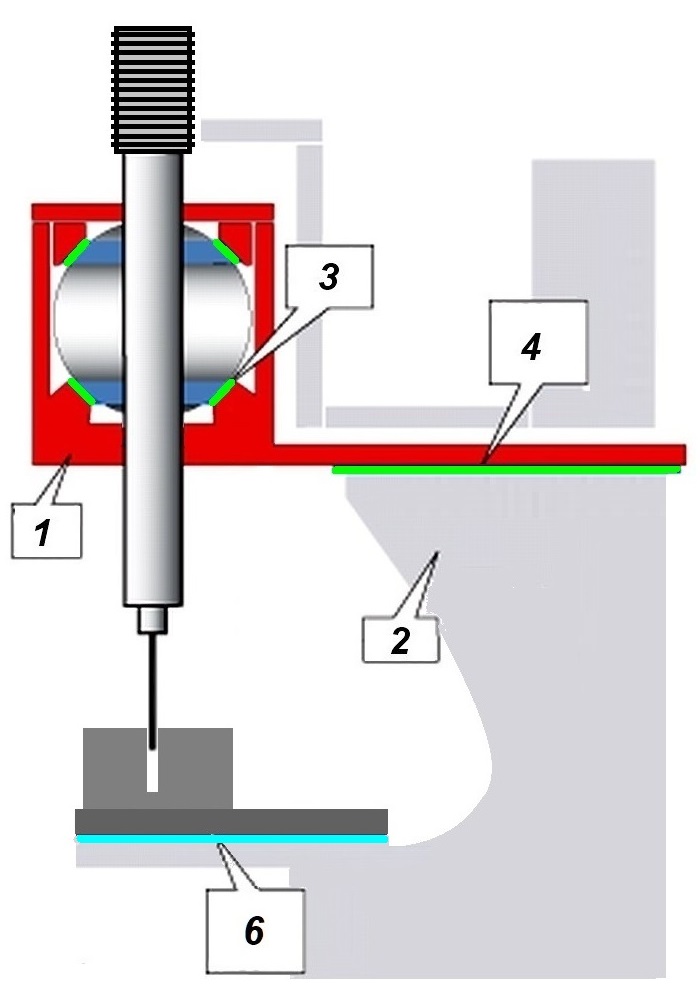
1 – frame, 2 – work table with the processed cylinder head, 3 – working headstock, 4 – air cushion of the working headstock, 5 – spindle hinge, 6 – magic bayonet
How to ensure concentricity? There are no problems at all – just take a slightly conical guide rod and firmly insert it into the valve guide (hence the name of the pilot — dead, that is, motionless). Then you can put a holder with a cutter on the pilot with a very small gap — and voila, everything is ready and precisely centered. Next, to sharpen, you will need to rotate the holder with the cutter, for which you should bring the spindle of the machine to the holder from above. Now you need to connect them so that there is no extra effort from the spindle to the holder — for this we put there … a special hinge, the so-called bayonet. And then the cutter, rotating on the pilot, will be 100500% concentric with the hole in the guide – bingo! It is impossible to even imagine simpler and more accurate!
And indeed, such a scheme, having appeared in America about 50 years ago, and its founder is considered, not without reason, to be the well-known American company ROTTLER, quickly gained popularity and distribution among manufacturers of repair equipment. And it gradually gained dominance in those countries where they realized that hand-to-hand, with toothed cutters and lapping, a cylinder head cannot be made well. And ROTTLER brand machines gradually became a model of precision and concentricity among repairmen all over the world.
And everything was fine and even just wonderful for them, as usual, when suddenly trouble came from where they did not expect it — in the 90s of the last century, cast iron, predominantly V-shaped monsters were replaced by light multi-valve engines. And you can no longer stick a large valve into such an engine — it will not fit. And the valves began to quickly decrease in size. But at the same time, it also unexpectedly turned out that the hinged scheme does not work as well as before…
It turned out that when the pilot size is reduced, the cutter, which seems to sit precisely and absolutely concentrically on it, no longer wants to cut the saddle concentrically. At the same time, the machine spindle, no matter how thick and rigid it is, does not help to solve the problem — the hinge, the same bayonet, interferes. As a result, when cutting forces appear from the cutter, the holder easily turns on the hinge, the thin pilot begins to bend, and the cutter is easily pressed away from the saddle. What happens in this case is clear — the cutter only strokes the saddle, does it beautifully, but cannot really fix anything.
A disaster, and nothing more. Everyone throws up their hands and scolds each other for not knowing how to use the best ROTTLER machines. And so it would have continued further, if another company had intervened in the matter — the French SERDI. Which proposed a fundamentally different scheme…
Option 2 — a rigid scheme for processing the seat
Main features (briefly):
1. Complex and rather “capricious” centering of the tool by the position of the pilot in the guide hole.
2. The pilot is used only as a “sensor” of the position during centering, it does not participate in the processing.
3. Extremely rigid system — the rigidity of the processing is determined by the thick spindle.
4. Complete versatility of the machine — the accuracy of the processing depends little on the size of the valve.


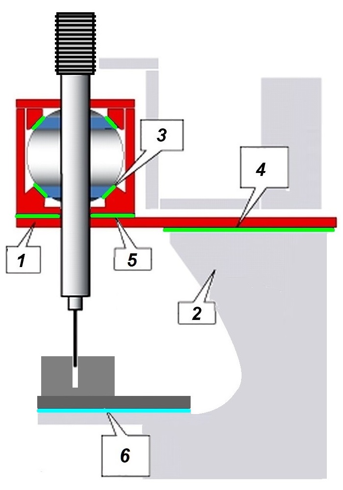
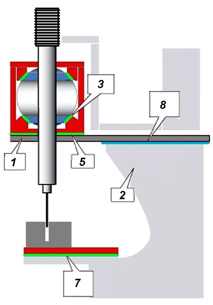
The rigid diagram (on the right) is no hinges and a live cylindrical pilot. Although some parts are similar:
1 – spindle, 2 – tool holder, 3 – pilot, 4 – bit holder, 5 – cutting bit, 6 – spring, 7 – valve guide, 8 – magic bayonet joint
When loaded with the same lateral force (from the cutting bit):

Results of computer modeling of the stress-strain state of cutting systems: in the hinged system, the holder rotates on a magic hinge and collects all the loads on a thin pilot (left), while in a rigid system, all the loads from the cutter are held by the thick spindle of the machine (right).
For small pilot diameters:

At small diameters of the pilot, with the rigidity of the hinged system, a real catastrophe occurs — the deformation from the cutting force goes off the scale, while in a rigid system there is almost no deformation
In fact, if the pilot is thin and bends so easily, then there is no need to hang any loads from the cutting bit on it — you just need to transfer all the loads to the machine spindle! And for this, you need to remove the bayonet hinge and connect of all the parts — the pilot, the holder with the cutter and the spindle, rigidly. For which, by the way, no conical dead pilot is needed — it just needs to be replaced with a live cylindrical one, let it now rotate in the hole of the valve guide!
Quite a sound idea, and by the way, this is how 99.9% of metalworking machines are made — the cutting bit is rigidly fixed to the spindle. And in general, it is strange that someone could have come up with such a crazy idea before — to put a hinge between the spindle and the cutter (you can imagine how surprised the engineers of the SERDI company were once). But it turned out that implementing their idea, which is no less obvious than that of the hinged scheme, is not so easy…
The main question is how to ensure the concentricity of the entire spindle with all its elements, and not just one holder with a cutter? Obviously, the spindle must be given complete freedom, but at the same time leave the guiding pilot as a sensitive element of the system — a concentricity (coaxiality) sensor, taking away all other power functions from it.
The solution to free the spindle from any loads was found quickly — everything must be placed on air cushions. There must be at least two of them — one spherical on the spindle, for its free tilt, and the other flat, for free horizontal movement of the working head with the spindle. However, it quickly became clear that this scheme is also insufficient for thin pilots — the working head of the machine is too heavy, and this has a bad effect on centering with small diameters of the pilots. The solution turned out to be not the easiest — the spindle itself inside the working head was placed on a separate small air cushion — the so-called cylinder sphere. And the spindle motor itself was reduced in size and hidden in the spindle…
Basic design schemes of centering in a rigid seat machining system:
A — with two air cushions (SERDI), B — with three air cushions (SERDI), B — with three air cushions (Provalve)
1 — work headstock, 2 — bed, 3- air cushion of the spindle sphere, 4- air cushion of the work headstock (participates in centering), 5 — air cushion of the sphere cylinder, 7 — air cushion of the table (only head installation), 7 — air cushion of the table (participates in centering), 8- air cushion of the work headstock (only head installation)
And it is this scheme — with 3 air cushions for spindle centering, that acquired unprecedented properties. It turned out that it practically does not matter what the pilot diameter is — it provides almost the same centering accuracy regardless of the diameter, making the machine truly universal and suitable for repairing any cylinder heads. And this is the main reason why gradually, year after year, the hinge-bayonet scheme began to lose supporters among machine tool manufacturers. Well, and when it came to the point that even the inventor of the bayonet scheme — the ROTTLER company, switched to a rigid scheme, completely abandoning the bayonet, we can confidently say that the time of dominance of hinge-bayonet machines has finally come to a logical end. As well as the time of disputes about which scheme — rigid or hinge-bayonet, is better.
Option 3. Some variations of the rigid processing scheme
1. Electronic modification
Some manufacturers went even further. Their main idea was to leave the pilot as a spindle position sensor, but transfer the executive centering function from the air cushions to the servo drives with software control.
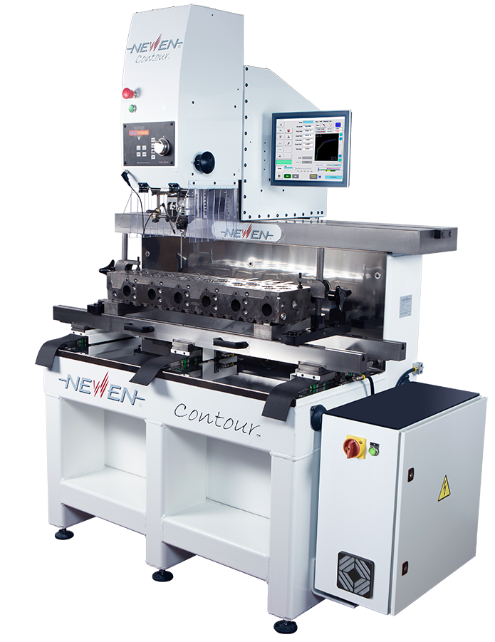
This is how the “electronic” modification of the rigid circuit appeared, and the machines of the American-French company NEWEN based on it are very precise and cool. However, nothing comes for free — their extreme complexity made them the most expensive. And everything was fine as long as crude mechanical bayonet machines dominated, which could not compete with software-electronic models. However, with the development and increasing distribution of rigid machines and, especially, with the advent of automated sensor control on them, it was the complexity and high price that led to the fact that machines using NEWEN technology became practically pointless to use in engine repair due to their lack of payback.
As a result, the use of these machines in repair gradually, year after year more and more, began to be reduced not to economic reasons, but to marketing — for example, as a way to squeeze out competitors by showing them your “coolness”. In addition, the principle of “point” processing instead of using traditional profile cutting bits played the worst joke on the manufacturer — the productivity of the most sophisticated NEWEN CNC machine fell below the most provincial cheap model with manual control. Which finally put an end to the use of the “electronic” modification of the rigid processing scheme in repair (leaving it for special applications — for Formula-1 engines and other spacecraft). In such a situation, this technology, having turned from practical to purely theoretical, went beyond the scope of this review and is not considered here.
2. Modification with a dead pilot
If you use a dead conical pilot instead of a cylindrical pilot in a rigid scheme, you can achieve some improvement in centering for cases where the gap of a live cylindrical pilot in the guide is increased (for example, a worn bushing). In this case, the dead pilot rotates in the same holder with which the cylindrical pilot is used.
Such options already exist (machines from Rossi & Kramer), but the advantage of this modification has not yet been confirmed. But in any case, it should be noted that the appearance of such a modification of the rigid processing scheme erases the difference between dead and living pilots. If previously dead pilots were the main feature of the bayonet, and living ones — of the rigid scheme, now the user can actually choose which pilots he likes best. And this is not only the main advantage of this scheme, but also its advantage over the bayonet, where the use of a living pilot looks, at the very least, strange, and therefore has not yet been implemented by anyone (which is not surprising — with a living pilot, the bayonet simply loses its meaning).
Part 3. PRACTICAL APPLICATION OF TECHNOLOGICAL PRINCIPLES: THE STATUS OF THE MARKET FOR MACHINES FOR PROCESSING SEATS IN ENGINE CYLINDER HEADS
A. Hinge-bayonet type machines
Previously, such machines were made by a large number of companies. But gradually their number decreased, and now there are only 8 of them left in the world — these are the Chinese THL, Indian Robins, Standard, Micron Mustafa, Manek, European AZ and Comec, as well as the Brazilian Chinelatto.
It is characteristic that all these machines are extremely similar, as if they were made in the same factory. However, despite the absolutely identical design, parameters and appearance, they are sold at completely different prices, which can differ by 1.5-2 or more times. The only exception is the newer models of the Robins company (the Indian name of the ROTTLER brand), which have touch control. And today this is the only company in the world trying to do the impossible — modernize machines with an outdated hinge-bayonet centering scheme — all other companies produce practically without changes the same ROTTLER model from half a century ago.

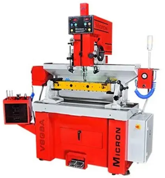
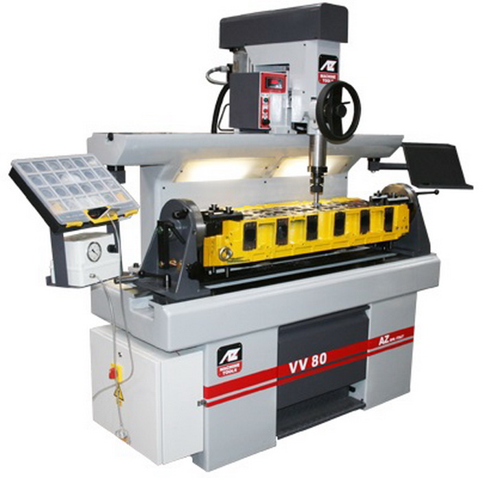
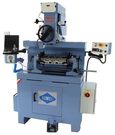
Twins and brothers, hinged machines with dead pilot: simple, inexpensive, fast. But not suitable for small valves
Main features of this type of machine:
1. Dead slightly conical pilot
2. Bayonet joint between the spindle and the cutting bit
3. Air cushion of the working head.
4. Hinged fastening of the spindle to the working head and a sensor for measuring its angle of inclination
5. Manual control whenconnecting the spindle with the cutter holder
6. Profile cutting bit
7. High productivity.
Main disadvantages:
1. A sharp drop in processing rigidity when the pilot diameter decreases to less than 7-8 mm
2. With small pilot diameters, this type of machine is only capable of smoothing the saddle, without correcting its geometry (but doing beautiful!)
Conclusions:
1. In fact, the machine was originally produced as a universal one, for any cylinder heads, but now it is morally obsolete and has become inapplicable for repairing cylinder heads of modern engines of cars and motorcycles. 2. At the same time, for engines with large valve diameters, this technology remains quite effective, including for engines of trucks and heavy equipment.
3. There is one more piece of good news — due to the fact that the vast majority of such machines are absolutely no different from each other, you can easily save on the purchase, sometimes even 2 times, by buying a cheaper model.
The specified features of the use of machines of this type must be known and taken into account when planning a purchase. If you neglect this, then there are already plenty of examples when people, without understanding and succumbing to advertising and idle advice, bought something completely different from what they wanted, and not at all for the work they planned. After which it was no longer clear what to do with such a purchase…
B. Rigid-type machines
If until recently such machines were produced only by the French company SERDI, and there were heated debates among repairmen about which machines were better and more accurate, now the number of manufacturers of rigid-type machines is already confidently starting to catch up with the number of those who are still clinging to the old.
The cheapest examples of rigid machines have long been mastered in China, and they are produced there by a number of companies (Tendtool, SJMC, THL, AMCO, BestWin) and are slightly modernized copies of the original SERDI machines of models 3.5 and 4.5, but at a price approximately 3 or more times cheaper. At the same time, the quality of Chinese fakes, oddly enough, is not so much worse the lower the price, and there are already examples of their more or less successful work. There are also more advanced models with touch screens and CNC, but there is no data yet on how effectively they work.

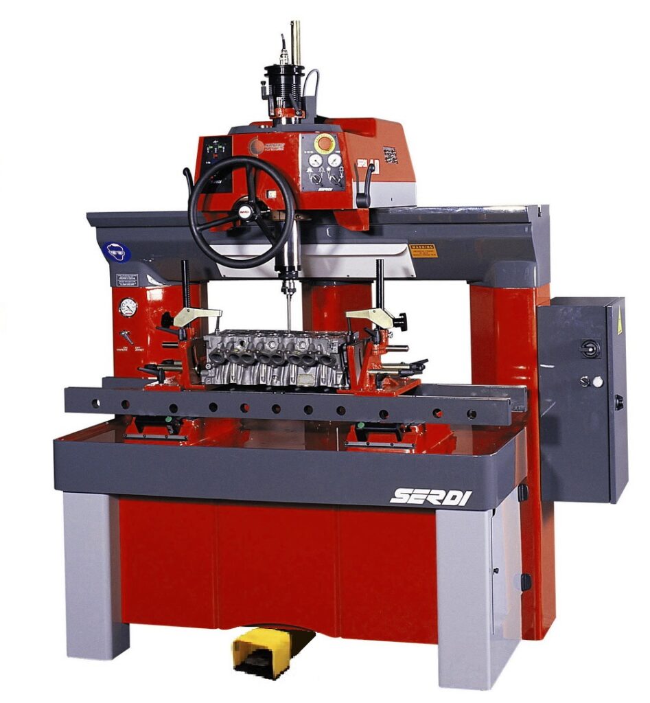
Despite being China (left), it works (amazingly, actually!). Although there is no data yet on how long it will work. The original thing (SERDI) on the right is the founder of the technology, repeatedly confirmed high accuracy and unrivaled reliability. But, unfortunately, 25 years of push-button manual control without any changes, except for an increase in price, is already a critical period and the beginning of rapid obsolescence…
As for the original SERDI, unfortunately, these machines have not changed in any way over the 25 years of their production (except for their price, which has been steadily increasing and has already begun to exceed some reasonable limits of payback). Therefore, there is some reason to believe that if they are not changed in any way in the near future, we will probably soon be able to observe the decline of this once famous company. However, we should pay tribute to the reliability and service life of these machines — it is already known that they can easily work for 20 years without a single failure. It is unlikely that anyone else can do this.
Among the Indian range of articulated machines, the Maxpreci company has firmly wedged itself with its two models of rigid machines. The details of their design are not disclosed, but most likely, they are made according to a simplified centering scheme — with a spherical half-spindle and one flat cushion of the working headstock. This scheme is not universal, it was previously used in the design of Italian machines of the now closed Italian company SERDI Srl and is more suitable for cargo heads. However, in any case, the production of such machines in India is a serious step forward.


The Indian Maxpreci machine (left) is made using the same centering scheme as the “defunct” SERDI Srl (right). Note: the Indian has a built-in spindle servomotor, while the Italian had a simple and heavy…
A definite step forward was made by the Italian company Rossi&Kramer. Its machines are the same simplified SERDI Srl scheme without a sphere cylinder cushion. However, the company confidently relied on a rigid scheme and has been constantly upgrading its machines for a number of years. Thus, a touch screen has already appeared on the bigger model. And it seems that if we add the above-mentioned ability to use any type of pilot, then the company can already be put in the ranks of the leaders in innovation. But there is a suspicion that the use of dead pilots was a forced price for a simplified centering scheme and an attempt to at least slightly improve the accuracy of centering on small diameters…
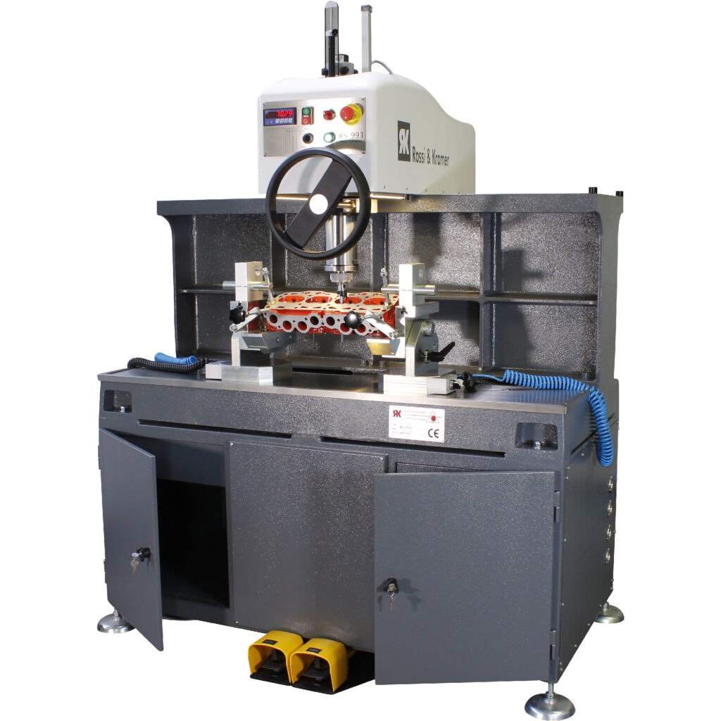
The Italian Rossi&Kramer probably is a good thing. Although there is a sense of incompleteness… Well, and the centering scheme with 2 air cushions will most likely not provide accuracy with small pilot diameters.
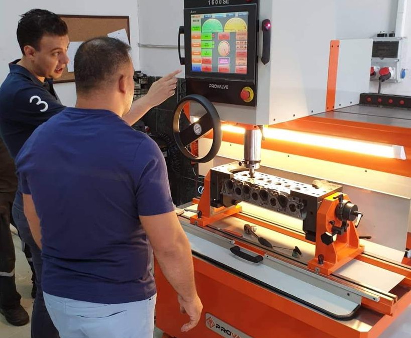
However, the leadership in this type of machine tools has gradually but surely been taken over by the Turkish brand Provalve. The only company that uses its own centering scheme with 3 air cushions, where instead of a working head cushion, a working table cushion is used. All models of this brand’s machines have not only touch control, but also patented automatic centering at the touch of a button, controlled by a PLC. Unlike the vast majority of other machines, Provalve machines implement the principle of full operator awareness of all operations and the state of the machine. These machines have many other innovations that are absent in traditional machines such as SERDI, while their price remains at an average and affordable level. As a result, Provalve machines have become widespread not only in Turkey and traditionally in the Middle East, but also in Europe, and there is already quite a lot of experience in the successful and fairly long-term use of these machines.
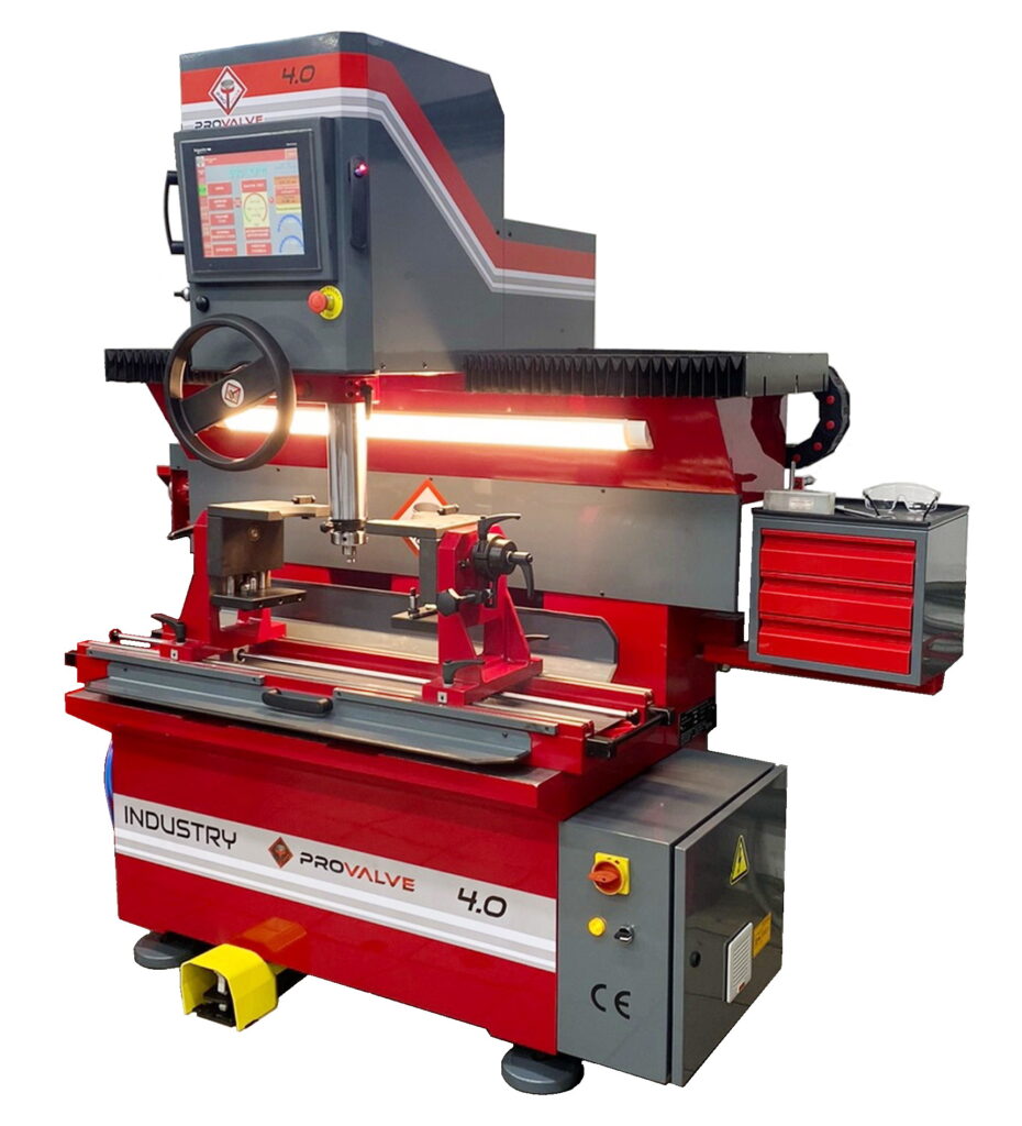
Turkish Provalve is today a leader in innovation. Touch control and automatic centering at the touch of a button, spindle tilt sensor, separate vacuum pump for quality control of processing, preliminary centering, in which, unlike machines like SERDI from other manufacturers, it is impossible to break the pilot, and even a built-in printer… The efficiency in repair, including accuracy, stability and reliability, has been confirmed many times, and it is very high
It is characteristic that the success of Provalve led to the fact that all other machine tool manufacturers in Turkey — Poleks, Saritas, and Honmaksan, quickly restructured, confidently moved from the production of bayonet machines to rigid ones and began to repeat Provalve almost like a carbon copy. Probably, in the hope of repeating the success itself. But, unfortunately, so far there is not enough data on the operation of their machines for processing saddles to make any reasonable conclusions.


Turkish guys Poleks and Saritas offer something electronic and sensory, but how it works, no one knows yet…
The American company ROTTLER unexpectedly found itself at the top of the chain of rigid machines. No matter how hard it tried to preserve the bayonet scheme — even camouflaged the magic bayonet inside the working headstock, but no — it had to give in and break on a spherical air cushion. And so much so that classic bayonet machines are no longer even visible in its production program. Apparently, it was not possible to squeeze anything out of the bayonet, when the last was already squeezed out (it is not even clear what will happen to the numerous supporters of bayonets now, after such a “betrayal”).
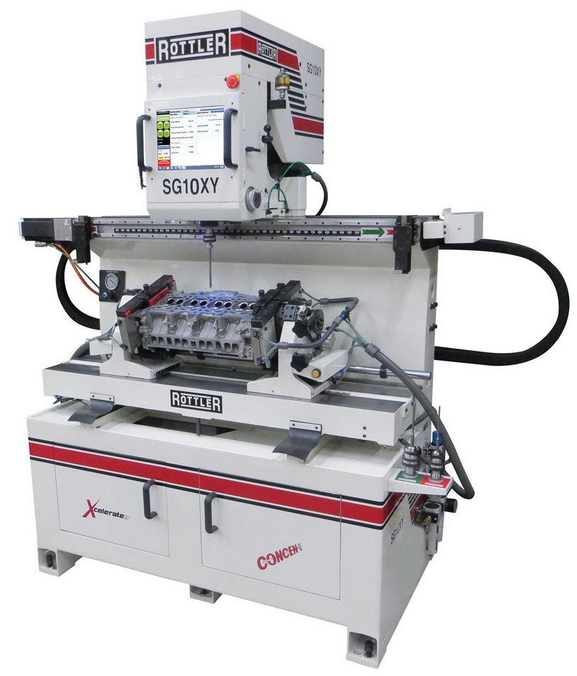
ROTTLER (left) and NEWEN (right) seem to be sworn competitors now. In CNC. And this area of science and technology is very far from repair…
It is impossible to say anything definite about the design of these machines — in the descriptions, the design is completely hidden behind magical and meaningless phrases about everything being patented (read — classified), and how the spindles furrow the expanses (float on air cushions), and then easily center themselves on the valve axis. Perhaps this description is enough for American repairmen, but one can doubt the accuracy of these machines if one reads in the description the phrase about the extraordinary lightness of the working head (which is not needed if there is a cylinder cushion of the sphere, but is very important in schemes like SERDI Srl, where there is no such cushion).
Nevertheless, the ROTTLER CNC control system is very advanced, as is the price of such machines. Which makes their real use in repairs a very, very problematic matter, if not to say — questionable, and especially in the absence of a detailed description of their design. Moreover, at their price level, rigid-type machines with a profile cutter and CNC have long been tested in all forms by the SERDI company, but have not found any real use in repairs. Therefore, another attempt to compete in a place where the NEWEN company has confirmed that there is no competition in principle due to the lack of demand, will most likely be just as disastrous.
And this is all that is on the world market for this type of equipment today.
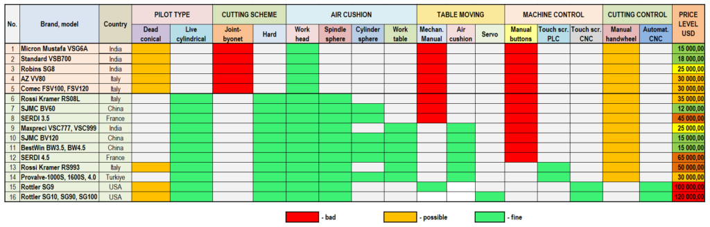
All of the above machines can easily be summarized in a table, where their features are most clearly visible:
Part 4. PROSPECTS AND FORECASTS OF THE MARKET OF MACHINES FOR SEAT PROCESSING
A. Basic requirements for a modern saddle machine:
1. Basic type — with a rigid processing scheme. Machines with a hinged scheme and dead pilots are obsolete and are not universal.
2. Guide pilot — live cylindrical. Dead conical can only be as an addition, if the machine allows it.
3. Three air cushions for centering the tool before processing — sphere, sphere cylinder, working headstock (or work table). Schemes with a smaller number of cushions involved in centering have limited processing accuracy at small valve diameters.
4. Spindle servomotor — ensures minimum spindle weight, which affects the accuracy of centering.
5. Air cushion of the work table — at least convenient for installing the cylinder head for processing.
6. Profile cutting bit — point cutting gives too low productivity.
7. Touch control with a clear interface is one of the main signs that the machine is modern and not outdated (although not the only sign, since there are already examples of installing touch screens on outdated articulated machines).
8. Process control system — the presence of sensors for spindle position (tilt), operating air pressure, spindle speed, air cushion condition, etc., relieves the operator from working blindly.
9. Automatic control modes — to reduce the impact of the operator’s qualifications on the quality of processing.
B. Recommendations for consumers:
1. Morally obsolete seat processing machines with dead pilots and bayonet joints are currently suitable only for trucks and heavy vehicles. At the same time, they are all made so identically that overpaying for the brand of some more famous manufacturer does not make any sense at all in terms of processing quality and productivity. 2. It is impossible to cheat the laws of physics in an attempt to use obsolete equipment for heads of modern cars and motorcycles; such an attempt will only lead to great disappointment for the “lucky” owner of an obsolete machine.
3. CNC machine tools for processing saddles are now so expensive that their payback is practically impossible. Their purchase for marketing reasons, as it was 15-20 years ago, has lost all practical sense. And if we take into account their low productivity and increased requirements for operator qualifications, then their purchase for repair currently has no reasonable justification at all.
4. Based on paragraphs 1-3, when it is necessary to repair a wide range of engines, universal equipment is required, which currently has no alternative but rigid seat processing machines with cylindrical pilots.
5. The technological capabilities of rigid machines have actually reached the limit of accuracy. And this is very high accuracy! However, it is important for the user to distinguish between the features of the device and the number of air cushions in the machine centering system to select the most optimal option.
6. Rigid machines with manual push-button control are gradually becoming obsolete and losing ground on the market. Therefore, given the growing problems with personnel, the most promising for use in repair of rigid-type machines with cylindrical pilots are those that are equipped with touch control and simple automatic functions.
Alexander Khrulev©
Dr.Eng.Sci., Senior researcher
*This article represents the author’s value judgment (opinion) on the topic discussed in the article and expresses a personal point of view that does not claim to provide irrefutable evidence or assert any indisputable facts. Accordingly, any use, in whole or in part, of the materials in this article must include a reference to the author’s value judgment.
